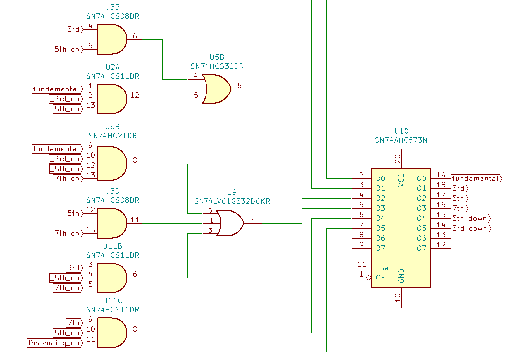
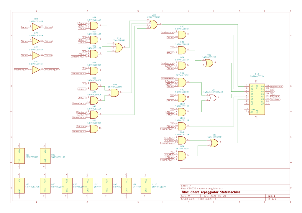
Previously in part 1 we diagramed a state machine to represent a chord arpeggio. In part 2 we determined what the sum of products would be for the state transition logic, and simulated the logic. Now it’s time for the next step which is to look at the physical implementation. I spent some time KiCAD and came up with this lovely schematic.
Ok so that’s 10 logic chips. We haven’t even looked at input conditioning, any manipulation of the clock that may need to be done, and actually generating an output control voltage from the various states. This is the point where I decide the module would be better implemented with a microcontroller, the scope expands out of control (because microcontrollers can do anything, why stop with 4-6 note sequences, why limit things to major and minor chords? What if I want to arpeggiate over a Cdim add 9 because I’m insane), and ultimately shelve the idea until a future date.
Last time I started designing a chord arpeggiator. We got as far as and articulating the specifications and then drawing a state machine to handle note transitions. Today we’ll try to minimize the gate count for transitioning between states and then simulate the logic using VHDL.
Logic Minimization
I decided to use Karnaugh Maps because I actually remember how to use them, and with only 8 variables the problem is still simple enough so that real logic minimization tools aren’t necessary yet. But ‘Aha!’ you say you have 10 variables 6 states and 4 inputs. Well since only one state can be active at a time the corresponding up and down states can be combined when working out the logic. To reduce typing I After working through the Karnaugh Map for each state I got this
States
Fundamental
Third
Fifth
Seventh
Fifth_down
Third_down
Inputs
Third_on
Fifth_on
Seventh_on
Decending_on
Logic
Fundamental = (not Third_on and not Fifth_on and not Seventh_on ) or (Third and not Fifth_on and not Seventh_on ) or ( Fifth and not Seventh_on and not Decending_on ) or ( Seventh and not Decending_on ) or ( Seventh and Decending_on and not Third_on and not Fifth_on ) or ( Fifth_down and not Third_on and Decending_on ) or ( Third_down and Decending_on )
Third = ( Fundamental and Third_on )
Fifth = ( Fundamental and not Third_on and Fifth_on ) or ( Third and Fifth_on )
Seventh = ( Fifth and Seventh_on ) or ( Third and not Fifth_on and Seventh_on ) or ( Fundamental and not Third_on and not Fifth_on and Seventh_on )
Fifth_down = ( Seventh and Fifth_on and Decending_on )
Third_down = ( Seventh and Third_on and not Fifth_on and Decending_on ) or ( Fifth_down and Third_on and Decending_on)
if I was actually good at digital design I’d be able to simplify that down to something ridiculous like 3 NAND and 2 XOR gates. But I’m not and that is a lot of logic which means there’s probably some errors in it and we should do a simulation.
Simulation
For simulating this type of glue logic I like to write a program for an FPGA and see how it runs. Of course I don’t have an actual FPGA or FPGA programming tool since they’re pretty spendy. So, I use the next best thing a web base FPGA simulator called EDA Playground because it’s free and easy to use. There are a variety of FPGA programming languages to choose from on EDA Playground. I picked VHDL because I remember how to use it the best of the available languages.
Link to EDA Playground arpeggiator simulation. While not my finest code it does show that the logic works. And EDA Playground provides a nice timing diagram for visualization.
Today’s Post is brought to you by my latest questionable module idea that probably only I am interested in. The idea is a four note chord arpeggiator. And not just four notes that would be boring I want to be able to toggle whether a note is played, toggle if the arpeggio is ascending only or will ascend and descend, and toggle some of the notes so the module can switch between major and minor chords and Major and Major 7 chords. Yes, I know just enough Baroque music theory to be dangerous. Back to the task at hand. And as always let’s try to do this without a microcontroller.
Specs
Up to 4 notes will be played
Notes 2-4 will be toggleable
Fundamental will be from CV input
2nd note is toggle able between major and minor 3rd
3rd note is a 5th above fundamental
4th note is toggleable between 7th and full octave
Output will be in 1 V/Octave
Changes to next note on clock pulse input
No micro
Design
If the module was going to transition between notes in a predictable order all the time we could use a shift register to handle the transitions. Since the transitions proposed are a little more complicated I decided to use a finite state machine to help design handle the transitions between notes.
What is a finite state machine? It is an abstract model of a system that can be in exactly one of a fixed number of states at a time. Such as a combination lock or a traffic light. Since we’ll only want to output one note of the chord at a time, and the clock input can indicate transition between notes/states, the state machine seems like a reasonable way to approach the problem.
Next we’ll need to simplify thing a little bit Since it is unlikely that both the major and minor third would be played in the same sequence I went ahead and grouped those into the same state. Likewise the seventh and full octave states were grouped. I decided to give descending fifth and thirds their own states. The alternative would be to use a separate ‘current direction’ state, but this way seems lazier. We’ve got 6 states and I suspect it will be easy to find an 8 bit register/d-flop/latch block so no worries there. With the states defined all that remains is defining the transitions between the states. For that we’ll need to articulate the module inputs. I’ve come up with four inputs affecting the state machine
3rd Active
5th Active
7th Active
Descending Active
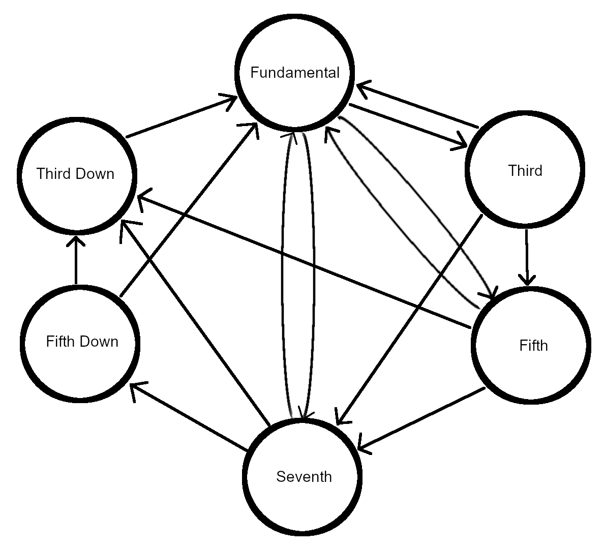
If the 3rd and 7th inputs are active and the 5th and Descending inputs are inactive that’ll produce note patterns of 1-3-7-1-3-7. If Descending is enabled the pattern will change to 1-3-7-3-1-3-7. This is going to get old fast so I’m just going to draw a graphical representation.
The circles represent the states the arrows represent possible transitions. If I were more ambitious I’d include some indication of the logic for each transition.
Join me next time when I start turning the graphical state machine into implementable logic.