Today’s Post is brought to you by my latest questionable module idea that probably only I am interested in. The idea is a four note chord arpeggiator. And not just four notes that would be boring I want to be able to toggle whether a note is played, toggle if the arpeggio is ascending only or will ascend and descend, and toggle some of the notes so the module can switch between major and minor chords and Major and Major 7 chords. Yes, I know just enough Baroque music theory to be dangerous. Back to the task at hand. And as always let’s try to do this without a microcontroller.
Specs
- Up to 4 notes will be played
- Notes 2-4 will be toggleable
- Fundamental will be from CV input
- 2nd note is toggle able between major and minor 3rd
- 3rd note is a 5th above fundamental
- 4th note is toggleable between 7th and full octave
- Output will be in 1 V/Octave
- Changes to next note on clock pulse input
- No micro
Design
If the module was going to transition between notes in a predictable order all the time we could use a shift register to handle the transitions. Since the transitions proposed are a little more complicated I decided to use a finite state machine to help design handle the transitions between notes.
What is a finite state machine? It is an abstract model of a system that can be in exactly one of a fixed number of states at a time. Such as a combination lock or a traffic light. Since we’ll only want to output one note of the chord at a time, and the clock input can indicate transition between notes/states, the state machine seems like a reasonable way to approach the problem.
Next we’ll need to simplify thing a little bit Since it is unlikely that both the major and minor third would be played in the same sequence I went ahead and grouped those into the same state. Likewise the seventh and full octave states were grouped. I decided to give descending fifth and thirds their own states. The alternative would be to use a separate ‘current direction’ state, but this way seems lazier. We’ve got 6 states and I suspect it will be easy to find an 8 bit register/d-flop/latch block so no worries there. With the states defined all that remains is defining the transitions between the states. For that we’ll need to articulate the module inputs. I’ve come up with four inputs affecting the state machine
- 3rd Active
- 5th Active
- 7th Active
- Descending Active
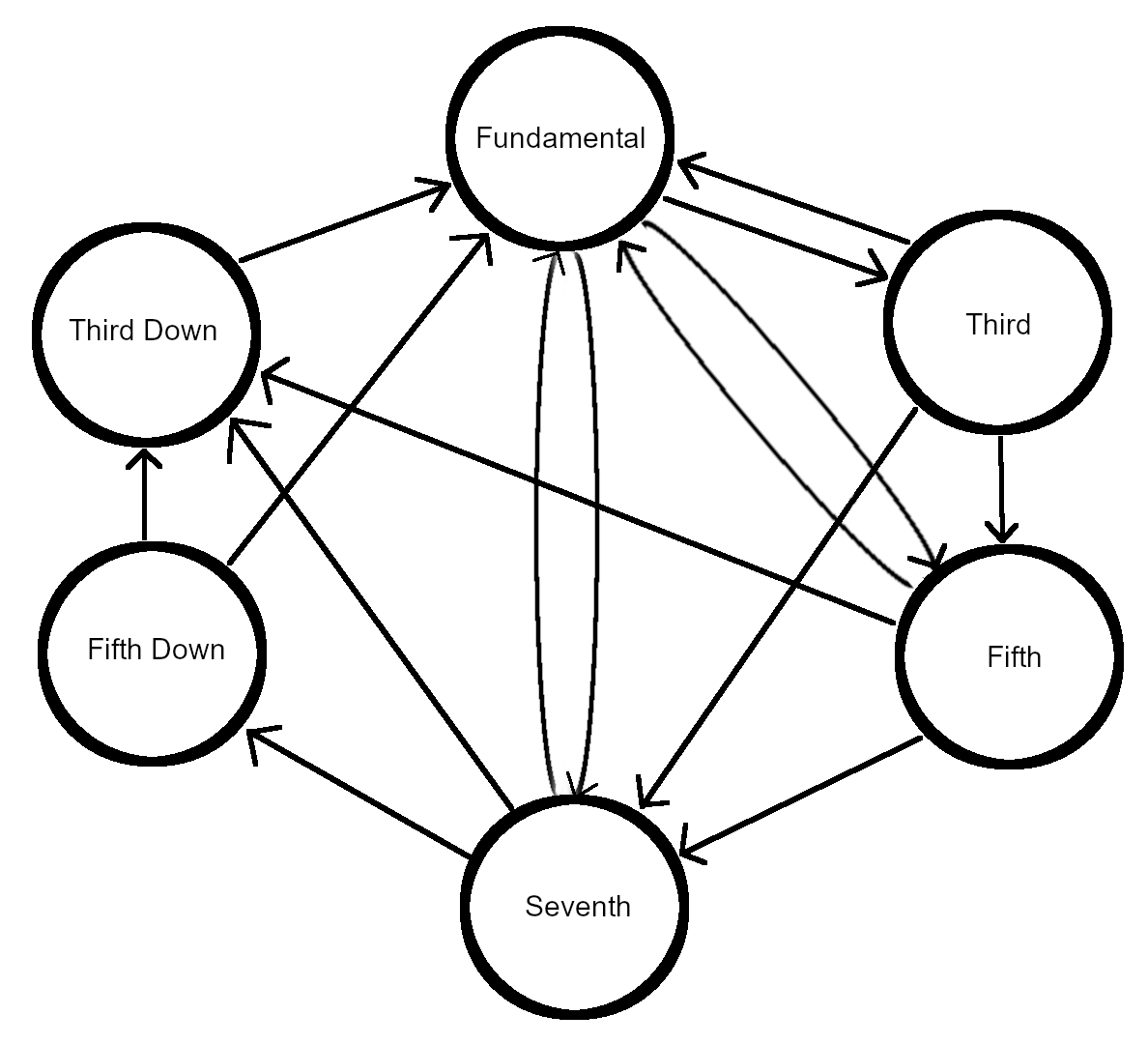
If the 3rd and 7th inputs are active and the 5th and Descending inputs are inactive that’ll produce note patterns of 1-3-7-1-3-7. If Descending is enabled the pattern will change to 1-3-7-3-1-3-7. This is going to get old fast so I’m just going to draw a graphical representation.

The circles represent the states the arrows represent possible transitions. If I were more ambitious I’d include some indication of the logic for each transition.
Join me next time when I start turning the graphical state machine into implementable logic.
