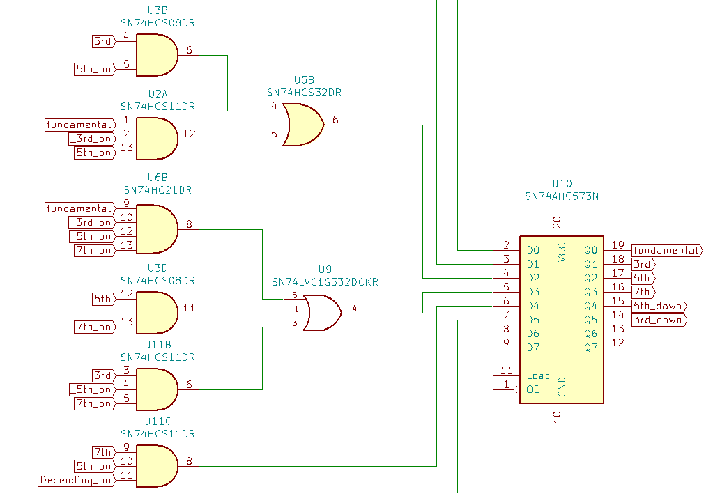
Previously in part 1 we diagramed a state machine to represent a chord arpeggio. In part 2 we determined what the sum of products would be for the state transition logic, and simulated the logic. Now it’s time for the next step which is to look at the physical implementation. I spent some time KiCAD and came up with this lovely schematic.
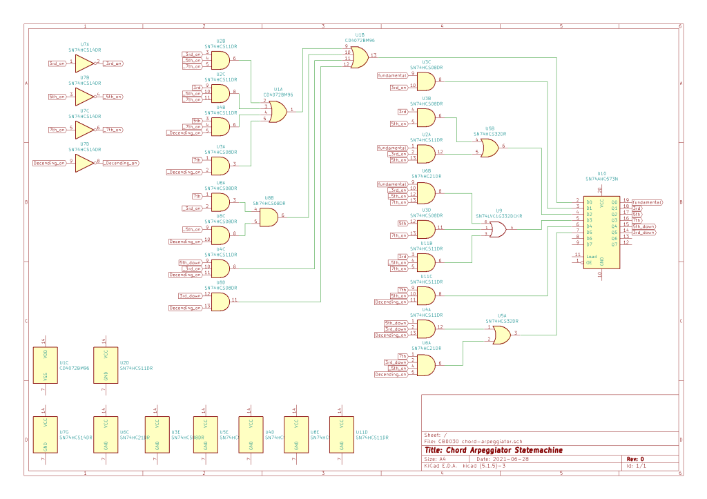
Ok so that’s 10 logic chips. We haven’t even looked at input conditioning, any manipulation of the clock that may need to be done, and actually generating an output control voltage from the various states. This is the point where I decide the module would be better implemented with a microcontroller, the scope expands out of control (because microcontrollers can do anything, why stop with 4-6 note sequences, why limit things to major and minor chords? What if I want to arpeggiate over a Cdim add 9 because I’m insane), and ultimately shelve the idea until a future date.
