Categories
DIY Mutable Instruments

Tides 2 LEDs

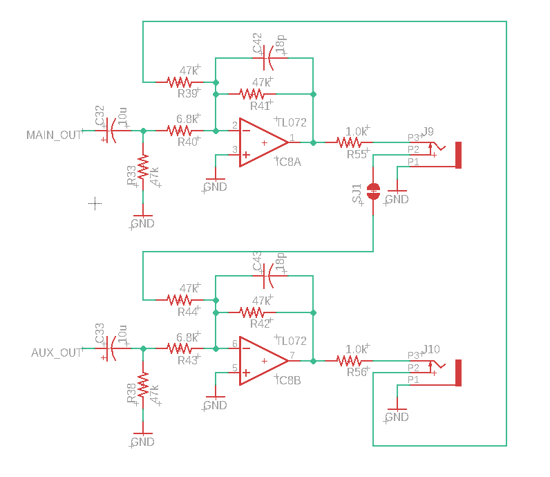
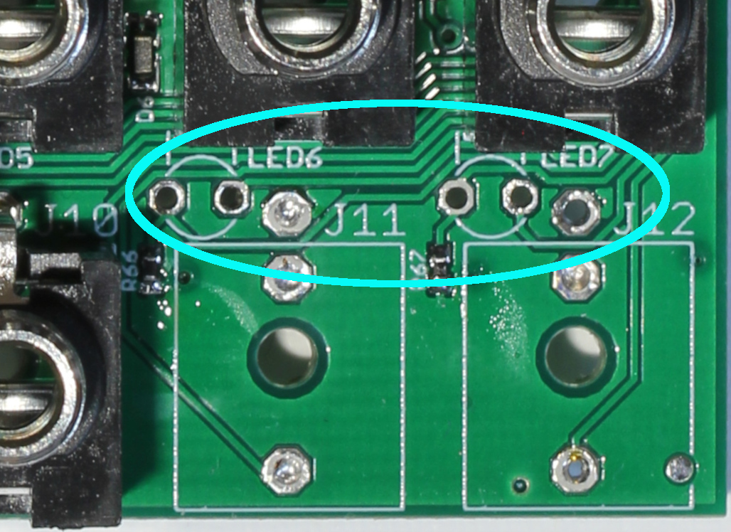
I’ve put together a few Mutable Tides 2 modules, and I think just about all of them have LED problems. Today we’re going to be looking at LED6 and LED7 which are among the audio jacks on the lower right of the board. As always it’s a good idea to look at the schematic.

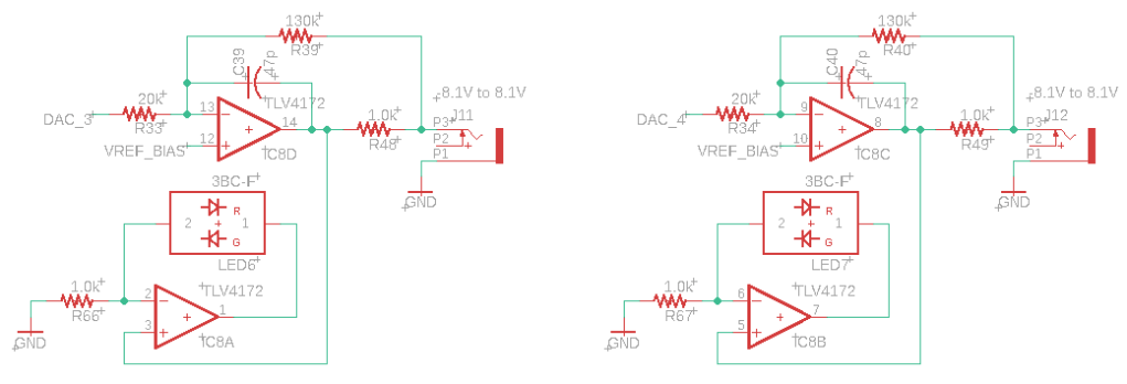
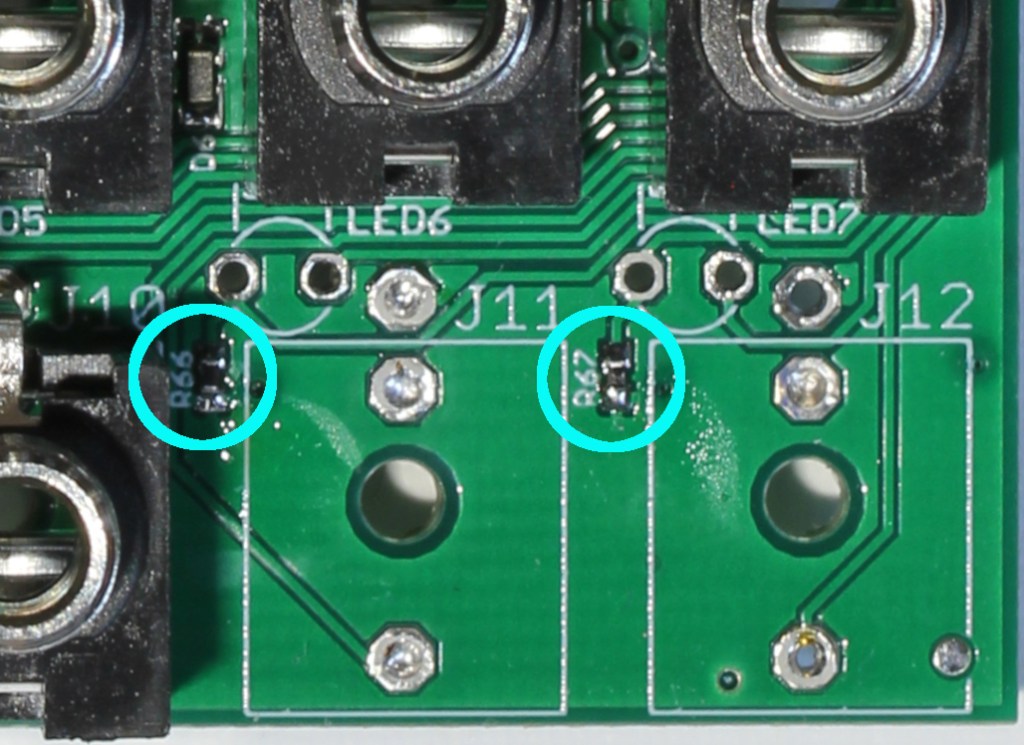
Not much going on here so it should be easy to troubleshoot. We’ve got a buffer amp driving the LED and a current limiting resistor. Circuits for LED6 and LED7 are duplicates which is nice since they’re probably suffering from the same problem. The first thing to do in these situations is to check the signal. I like to start with the op amp to make sure it’s outputting something. Next making sure Pin 1 on the LED matches the op amp output will give you an idea of trace integrity. Since the signal to pin one of the LEDs looked good I assumed the LEDs must be bad and removed them. And this was wrong. With the LEDs out it became apparent that the LED Pin 2 net was floating. And connecting the LEDs to my bench supply showed they worked fine. So the actual culprits here were the R66 and R67 resistors which had bad solder joints. Visual inspection showed that the resistors were slightly misplaced and only one solder joint had formed properly. After removing the J11 and J12 jacks this was easily fixed by adding a little more solder.

Tides 2 R66 and R67 on the PCB

If I could remember how soldering this board went a few months back I suspect these resistors tombstoned. Tombstoning is when one terminal of a two terminal part lifts into the air during solder reflow. In the classic example the part stands perpendicular to the face of the PCB and looks like a tombstone.

Tombstoned SMD resistors, Courtesy of O-fey and Wikimedia commons

Primarily tombstoning has to do with asymmetrical heating of the pads for small surface mount components. Since Tides 2 uses almost entirely 0402 sized passives and I reflow solder the boards on a hotplate with a noticeable temperature gradient between the center and the edge, I had quite a few tombstoned parts.

One of the things I like about reflowing on a hot plate is it’s easy to adjust parts while the solder is melted. So I can just tilt tombstoned parts back into position with some tweezers and forget about them. Unfortunately with parts this small it’s easy to knock the parts out of alignment and miss one of the solder pads. The lesson here is I should be better about using a microscope during reflow.

Categories
LRR Eurorack Modules

JVCA Eurorack Module

This Eurorack module contains 2 JFET based voltage-controlled amplifiers (VCA). VCA’s are a core component in synths. They’re commonly used in conjunction with an envelope generator for shaping
sounds, or with two oscillators for tone synthesis. The inputs and outputs are buffered using fast professional audio grade op-amps to maintain signal integrity and performance.

Specs

SizeWidth: 4 HP
Depth: 42 mm
Power360 mW
12 V15 mA
-12 V15 mA
Channel
Definitions
1 (knob)User control knob/
CV DC offset
2 (CV)Control Voltage
0 to 5 V range
3 (SIG:IN)Input Signal
-5 to +5 V range
4 (SIG:OUT)Output Signal

Power

The module uses a standard 10 pin Eurorack connector with polarity marked

Inputs and Outputs

1. Knob

Adds a DC offset from 0 to 5 volts to the control voltage.

2. CV

This is the control voltage gain input, and it is normalized to 0 V. The recommended input range is 0 to 5 V. Voltages less than 0 will have the same gain as 0 V, and Voltages greater than 5 V will have the same gain as 5 volts.

3. Sig:In

The signal input is DC-coupled and will accept audio or CV signals. The recommended input range is -5 to +5 V. Voltages outside this range will cause increased distortion.

4. Sig:Out

Signal output

Inputs are tolerant to voltages from -12 V to + 12 V. Exceeding this range will damage the module.

Gain Response

The response of the VCA is exponential. A representative plot showing gain vs control voltage is shown in Figure 1.

Figure 1. Gain vs Control Voltage

Categories
DIY Mutable Instruments

Mutable Instruments Rings: Should the SJ1 pads be bridged?

So you want to DIY a Mutable Instruments Module

This is going to be the first in what I anticipate will be a series of posts I’m tentatively titling ‘So you want to DIY a Mutable Instruments Module’. When I started designing Eurorack modules I decided to put together a few DIY modules to learn about common components and design patterns. The modules I picked to DIY were designed by Mutable Instruments. Mutable Instruments has designed a line of top quality Eurorack modules, and because they’re better people than I am, all of their designs are open source. That’s right schematics, bills of materials, PCB layouts, cover panel designs, and software source files are all easily downloadable from GitHub. I generally consider the documentation to be quite good. However there always seems to be something fiddly that doesn’t work quite right for the first one you assemble. And I’m going to discuss the solutions to the questions and problems I had while I was assembling the modules.


Back to the actual topic, the solder jumper on Rings

On the Rings module there is a solder jumper, SJ1, with no clear indication if it is supposed to be shorted or left open. Since the pad is wedged between two mono jacks it is best to pick its state during assembly. What should we pick?

Short version: short the jumper

The longer version:

To answer this question we need to know two things: What does SJ1 do? How is this module expected to function when it passes QC at Mutable? The first question should be pretty easy to answer; we’ll just take a quick look at the circuit schematic.

This section of the schematic covers SJ1, IC8 (output opamp) J9 (Odd output), and J10 (Even output). SJ1 connects the switched pin on Odd output to the amplifier mix for the Even output. Interestingly there is no solder jumper in the connection between the switched pin on the Even output and the Odd amplifier mix. So SJ1 causes the Odd output to be mixed with the even output if no cable is connected to the Odd jack.

Is this desired behavior? Fortunately we’re in luck and this is covered in the official manual for Rings no digging required.

Mutable Instruments rings manual

5. Odd and even audio outputs. In monophonic mode, these two outputs carries two complementary components of the signal (odd and even numbered partials with the modal resonator, dephased components due to picking position and pickup placement with the string resonators). In polyphonic mode, splits the signal into odd and even numbered strings/plates. Note that you need to insert a jack into each output to split the signals: when only one jack is inserted, both signals are mixed together.


The final sentence tells us what we need to know. “Note that you need to insert a jack into each output to split the signals: when only one jack is inserted both signals are mixed together.” So the factory default is both signals are mixed when only one output jack is used therefore we need to bridge the solder jumper SJ1.

Categories
LRR Eurorack Modules

Mid Side Module

This Eurorack module enables mid side processing. The top portion of the module converts left and right stereo signals into mid and side components for filtering or other effects. The bottom portion of the module converts the mid and side signals back into left and right stereo components. Mid and Side out are internally connected to Mid and Side in respectively (normalized). These connections are severed if cables are connected to the Mid and Side inputs respectively. The module uses professional audio quality amplifiers which are both fast and have low noise insertion so the module imparts minimal color to the processed signals.

Specs

Width4 HP 
Depth54.5 mm
Power0.38 W
+12 V16 mA
-12 V16 mA

Channel Definitions

L<Left in (Lin)
R<Right in (Rin)
M>Mid out (Lin + Rin)/2
S>Side out (Lin– Rin)/2
M<Mid in (Min)
S<Side in (Sin)
L>Left out (Min + Sin)
R>Right out (Min – Sin)

Connecting

The module uses a standard 10 pin eurorack connector with polarity marked. 

Filter ideas

Uniform Filtering

Separate Mid and Side apply similar filters to both channels before remixing. This minimizes unwanted distortions in left and right channels from using filters that aren’t perfectly matched.

Center the base

Separate mid and side, then apply a high pass filter to the side channel before remixing to left and right. 

Add space

Separate Mid and Side, then apply reverb to the side channel, before remixing to left and right

Control Voltage Mixing

Average
Average+
Sum
Average-
Difference
Half Differential+