So you want to DIY a Mutable Instruments Module
This is going to be the first in what I anticipate will be a series of posts I’m tentatively titling ‘So you want to DIY a Mutable Instruments Module’. When I started designing Eurorack modules I decided to put together a few DIY modules to learn about common components and design patterns. The modules I picked to DIY were designed by Mutable Instruments. Mutable Instruments has designed a line of top quality Eurorack modules, and because they’re better people than I am, all of their designs are open source. That’s right schematics, bills of materials, PCB layouts, cover panel designs, and software source files are all easily downloadable from GitHub. I generally consider the documentation to be quite good. However there always seems to be something fiddly that doesn’t work quite right for the first one you assemble. And I’m going to discuss the solutions to the questions and problems I had while I was assembling the modules.
Back to the actual topic, the solder jumper on Rings
On the Rings module there is a solder jumper, SJ1, with no clear indication if it is supposed to be shorted or left open. Since the pad is wedged between two mono jacks it is best to pick its state during assembly. What should we pick?
Short version: short the jumper
The longer version:
To answer this question we need to know two things: What does SJ1 do? How is this module expected to function when it passes QC at Mutable? The first question should be pretty easy to answer; we’ll just take a quick look at the circuit schematic.
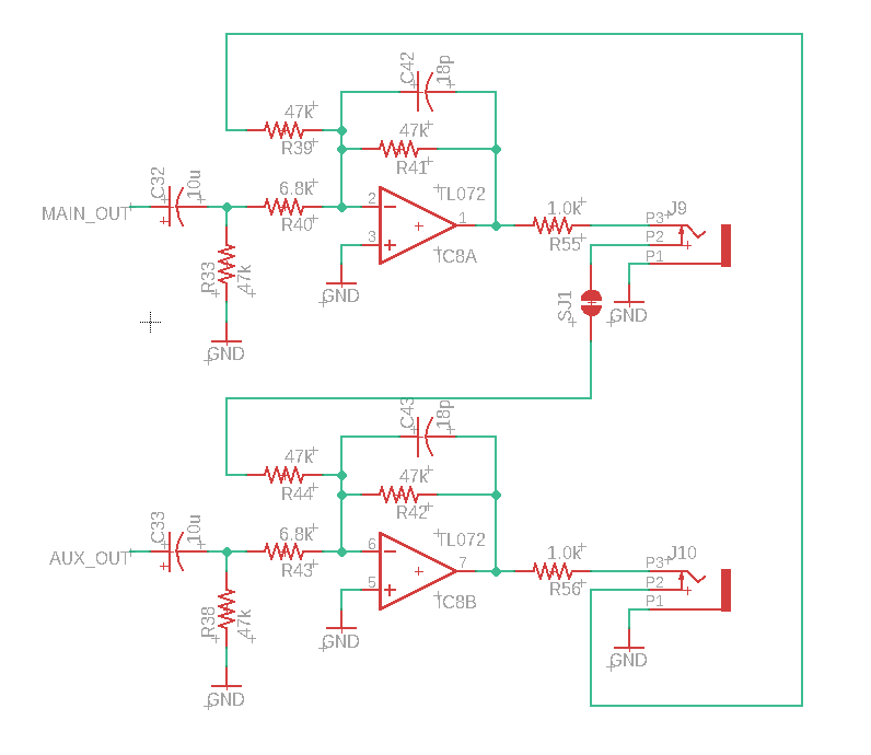
This section of the schematic covers SJ1, IC8 (output opamp) J9 (Odd output), and J10 (Even output). SJ1 connects the switched pin on Odd output to the amplifier mix for the Even output. Interestingly there is no solder jumper in the connection between the switched pin on the Even output and the Odd amplifier mix. So SJ1 causes the Odd output to be mixed with the even output if no cable is connected to the Odd jack.
Is this desired behavior? Fortunately we’re in luck and this is covered in the official manual for Rings no digging required.
Mutable Instruments rings manual
5. Odd and even audio outputs. In monophonic mode, these two outputs carries two complementary components of the signal (odd and even numbered partials with the modal resonator, dephased components due to picking position and pickup placement with the string resonators). In polyphonic mode, splits the signal into odd and even numbered strings/plates. Note that you need to insert a jack into each output to split the signals: when only one jack is inserted, both signals are mixed together.
The final sentence tells us what we need to know. “Note that you need to insert a jack into each output to split the signals: when only one jack is inserted both signals are mixed together.” So the factory default is both signals are mixed when only one output jack is used therefore we need to bridge the solder jumper SJ1.
