So you want to DIY a Mutable Instruments Module
A few months ago, I was assembling a Mutable Instruments module (let’s assume it was Rings), and I was about to place the microcontroller. We all know that Pin 1 IC packages are marked with some sort of dimple, dot, or indentation. For example

However, this microcontroller had two two dimples.
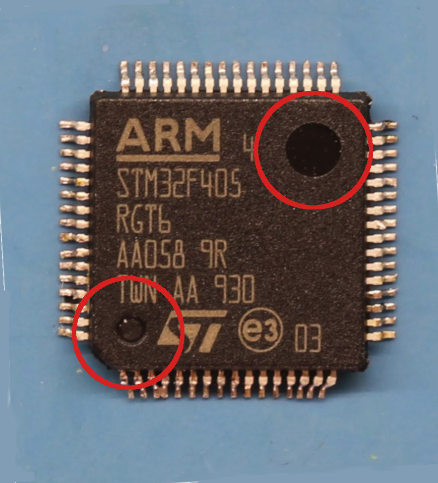
So which one marks Pin 1? If you’re literate you read the datasheet, and note that Pin 1 is denoted by the dimple at the bottom left of the text marking.

If you’re illiterate, like me, you ignore the datasheet, decide that pin one must be the big dimple near the top of the text, install the part backwards, rage at the world when the module doesn’t work., heat gun the micro controller off, replace it with a new IC oriented correctly, and then wonder why you weren’t smart enough to read the documentation in the first place.
The moral of todays story is when in doubt read the documentation. In fact just read the documentation, always.
